 Lexus V8 Engines LLC
11-Pin 80 Series Transfer Case Client Plug Guide
80 Series Land Cruiser Transfer Case Control Reference
Transfer case / center differential lock vehicle-side interface
Build-Specific Confirmation
Always confirm connector orientation, terminal location, wire color, circuit function, signal direction, polarity, fuse protection, and build-specific instructions before final installation. Do not wire by color alone.
Connector Visuals
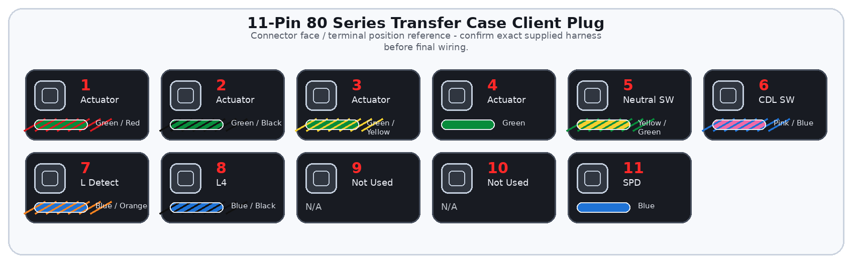
Overview
The 11-pin transfer case client plug provides customer-side wiring points for transfer case actuator/control motor circuits, transfer neutral detection, center differential lock detection, transfer low/L4 status, and the SPD signal where required.
The purpose of this plug is to keep transfer case wiring separate from the main engine, transmission, OBD2, and cruise control client plugs.
Important
This guide covers the 11-pin transfer case client plug used to connect a Lexus V8 Engines LLC standalone harness into the existing 80 Series Land Cruiser transfer case and center differential lock vehicle-side circuit. This plug is a transfer case control interface only; it does not replace the Toyota chassis harness, dash indicator wiring, fuse circuits, or factory vehicle-side control circuit.
General Information Notice
This document is provided for general information and customer reference only. Final wiring must be verified against the exact harness supplied and the vehicle-side circuit being connected.
Quick Start: Critical Connections
| Function Group | Circuit / Pin | Wire(s) | Customer Connection |
|---|---|---|---|
| Transfer Actuator | Actuator control circuits | Pins 1-4 | Connect into the correct 80 Series actuator/control motor circuits. |
| Transfer Neutral Detection | Neutral position switch | Pin 5 | Connect to transfer neutral position detection switch. |
| Center Diff Lock Detection | Center diff lock switch | Pin 6 | Connect to center differential lock detection switch. |
| Transfer L Detection | Transfer low position switch | Pin 7 | Connect to transfer L/low-range detection switch. |
| L4 Circuit | L4 | Pin 8 | Connect to existing vehicle-side L4 circuit as configured. |
| Vehicle Speed | SPD | Pin 11 | Provide required speed signal where applicable. |
Wire Color / Tracer Reference
Stripe/tracer colors are shown as diagonal bands on the wire. The first color is the base wire color. The second color is the stripe/tracer color.
Full Pinout Reference
| Pin | Wire Visual | Circuit / Function | Signal Type | Notes |
|---|---|---|---|---|
| Pin 1 | Green / Red | To Actuator | Transfer actuator circuit | Connect only to the correct 80 Series actuator/control motor circuit for the supplied harness. |
| Pin 2 | Green / Black | To Actuator | Transfer actuator circuit | Do not use as general power or ground. |
| Pin 3 | Green / Yellow | To Actuator | Transfer actuator circuit | Confirm vehicle-side actuator/control motor pin location before final connection. |
| Pin 4 | Green | To Actuator | Transfer actuator circuit | Confirm actuator connector and transfer case type before operation. |
| Pin 5 | Yellow / Green | Detection SW | Transfer neutral position | Transfer neutral detection switch input/status circuit. |
| Pin 6 | Pink / Blue | Detection SW | Center diff lock | Center differential lock detection switch input/status circuit. |
| Pin 7 | Blue / Orange | Detection SW | Transfer L position | Transfer low-range position detection switch input/status circuit. |
| Pin 8 | Blue / Black | L4 | Transfer L4 circuit | Confirm exact signal direction and polarity for the supplied harness. |
| Pin 9 | N/A | Not Used | N/A | No customer connection shown. |
| Pin 10 | N/A | Not Used | N/A | No customer connection shown. |
| Pin 11 | Blue | SPD | Vehicle speed signal | Speed signal used by transfer case control logic where applicable. |
Detailed Circuit Notes
Actuator circuits
- Do not assume actuator wires are interchangeable. Incorrect wiring can move the actuator in the wrong direction or damage the system.
- Do not apply direct battery power or ground unless a build-specific test procedure calls for it.
Detection circuits
- Verify transfer neutral, center diff lock, and transfer low states with a multimeter or scan data where available.
- Incorrect detection switch wiring can cause flashing indicators, no confirmation, or control logic faults.
L4 and speed
- Confirm whether L4 is switched input, indicator/status line, ground-switched, or voltage-switched for the exact build.
- Confirm SPD source and pulse rate before final connection.
First Test Checklist
| Item | Check |
|---|---|
| Actuator pins | Pins 1-4 are connected to the correct actuator/control motor terminals. |
| Neutral detection | Pin 5 changes state only in transfer neutral. |
| CDL detection | Pin 6 confirms center diff lock status correctly. |
| L detection / L4 | Pins 7 and 8 show correct low-range/L4 state. |
| SPD | Speed signal is present and compatible if required. |
Troubleshooting Quick Reference
| Symptom | Items to Check |
|---|---|
| No 4WD operation | Check actuator wiring, transfer case ECU/control power, detection switches, and grounds. |
| Incorrect range indication | Check neutral, low-range, and L4 detection circuit states. |
| Speed-related control issue | Check SPD source, signal type, and pulse rate. |