 Lexus V8 Engines LLC
6 & 4-Pin Pass-Through Harness Guide
Manual Applications – Transmission Sensor Pass-Through Reference
Transmission-side switch and sensor pass-through wiring
Build-Specific Confirmation
Always confirm connector orientation, terminal location, wire color, circuit function, signal direction, polarity, fuse protection, and build-specific instructions before final installation. Do not wire by color alone.
Connector Visuals
Overview
Use this harness when a transmission-mounted switch or sensor must be routed from the rear of the engine harness into the cab. Typical examples include reverse switch wiring, neutral switch wiring, vehicle speed signal routing, range or transfer-case switch signals, and indicator/relay trigger circuits.
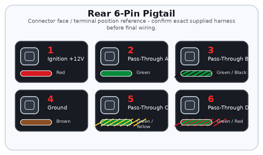
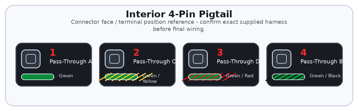
The rear 6-pin pigtail provides ignition positive, ground, and four pass-through signal wires. The interior 4-pin pigtail carries only the four matching pass-through wires into the cab.
Important
This guide explains the rear 6-pin and interior 4-pin pass-through pigtails supplied with certain manual-application standalone harness builds. These pigtails provide a clean route for low-current transmission-side signals into the vehicle interior. They are not a transmission harness, body harness, or chassis wiring replacement.
General Information Notice
This document is provided for general information and customer reference only. Final wiring must be verified against the exact harness supplied and the vehicle-side circuit being connected.
Quick Start: Critical Connections
| Function Group | Circuit / Pin | Wire(s) | Customer Connection |
|---|---|---|---|
| Identify Device | Reverse, neutral, speed, or other low-current signal | Rear 6-pin | Confirm whether the device needs power, ground, or signal only. |
| Power / Ground | Ignition positive and ground | Rear Pin 1 / Pin 4 | Use only if required by the transmission-side circuit. |
| Signal Routing | Pass-Through A-D | Rear Pins 2,3,5,6 to Interior Pins 1,4,2,3 | Route the selected signal into the cab using the matching interior wire. |
| Final Test | Continuity and isolation | Both pigtails | Check continuity end-to-end and confirm no shorts before powering the circuit. |
Wire Color / Tracer Reference
Stripe/tracer colors are shown as diagonal bands on the wire. The first color is the base wire color. The second color is the stripe/tracer color.
Full Pinout Reference
| Pin | Wire Visual | Circuit / Function | Signal Type | Notes |
|---|---|---|---|---|
| Rear Pin 1 | Red | Ignition Positive | Switched +12V supply | Available at rear pigtail for transmission-side circuits that require ignition power. Use fuse protection and do not overload. |
| Rear Pin 2 | Green | Pass-Through A | Low-current pass-through | Matches Interior Pin 1. |
| Rear Pin 3 | Green / Black | Pass-Through B | Low-current pass-through | Matches Interior Pin 4. |
| Rear Pin 4 | Brown | Ground | Ground supply | Ground available for sensor/switch circuits. Do not use as a high-current chassis ground. |
| Rear Pin 5 | Green / Yellow | Pass-Through C | Low-current pass-through | Matches Interior Pin 2. |
| Rear Pin 6 | Green / Red | Pass-Through D | Low-current pass-through | Matches Interior Pin 3. |
| Interior Pin 1 | Green | Pass-Through A | Interior signal | Source: Rear Pin 2. |
| Interior Pin 2 | Green / Yellow | Pass-Through C | Interior signal | Source: Rear Pin 5. |
| Interior Pin 3 | Green / Red | Pass-Through D | Interior signal | Source: Rear Pin 6. |
| Interior Pin 4 | Green / Black | Pass-Through B | Interior signal | Source: Rear Pin 3. |
Detailed Circuit Notes
Low-current signal use
- Do not use pass-through wires to directly power lamps, fans, pumps, compressors, motors, or other high-current loads.
- Use the pass-through wire as a relay trigger when the controlled load requires higher current.
Verification
- Confirm wire labels and pin positions on the exact harness supplied.
- Test continuity from rear pigtail to interior pigtail before final connection.
- Check that power and ground are isolated from all pass-through signal wires.
First Test Checklist
| Item | Check |
|---|---|
| Continuity | Each rear pass-through wire matches the correct interior pin. |
| Isolation | No pass-through wire is shorted to power, ground, or another pass-through wire. |
| Load Control | High-current loads are controlled through relays, not directly through pass-through wires. |
Troubleshooting Quick Reference
| Symptom | Items to Check |
|---|---|
| Signal does not reach cab | Check rear-to-interior continuity and confirm the correct matching pin. |
| Fuse blows or wire gets hot | A high-current load may be connected directly; rewire through a relay. |
| Sensor behaves incorrectly | Confirm whether the sensor requires ignition power, ground, pull-up, or signal only. |