 Lexus V8 Engines LLC
10-Pin Client Plug Guide
Manual Application Standalone Engine Harness Reference
Main vehicle-side engine harness client plug
Build-Specific Confirmation
Confirm fuel pump strategy, warning-light strategy, A/C control wiring, OBD2 details, terminal locations, wire colors, and exact harness labels before final installation. Use one fuel pump strategy only: Pin 7 direct pump output or Pin 8 FC relay trigger. Do not connect Pin 7 and Pin 8 together.
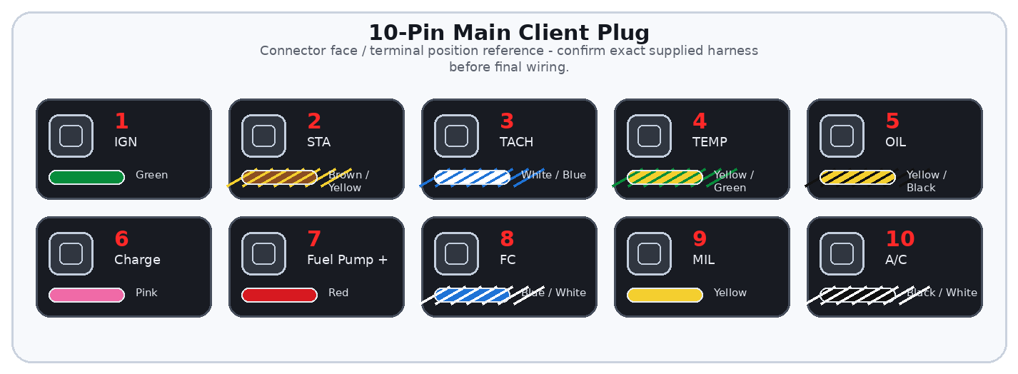
Connector Visuals
Overview
The 10-pin client plug keeps the basic vehicle-side engine connections in one clean, serviceable connector. It includes ignition power, start signal, tach, temperature, oil, charge light, fuel pump control options, MIL/check engine light, and A/C control.
Only three basic connections are normally required to start and run the engine: IGN, STA, and one fuel pump control strategy. The remaining circuits support gauges, warning lights, A/C, and diagnostics/vehicle integration.
Important
This guide explains the vehicle-side 10-pin client plug supplied with Lexus V8 Engines LLC standalone engine harness systems. It covers the connections normally required to start, run, and monitor the engine in a manual application.
General Information Notice
This document is provided for general information and customer reference only. Final wiring must be verified against the exact harness supplied and the vehicle-side circuit being connected.
Quick Start: Critical Connections
| Function Group | Circuit / Pin | Wire(s) | Customer Connection |
|---|---|---|---|
| Ignition Power | IGN | Pin 1 | Switched +12V in key ON and CRANK. |
| Start Signal | STA | Pin 2 | +12V only during cranking. |
| Fuel Pump Option A | Fuel Pump + | Pin 7 | Direct fused +12V fuel pump output if this harness strategy is supplied. |
| Fuel Pump Option B | FC | Pin 8 | Toyota-style ECU-controlled ground trigger for a fuel pump relay. Do not connect to Pin 7. |
Wire Color / Tracer Reference
Stripe/tracer colors are shown as diagonal bands on the wire. The first color is the base wire color. The second color is the stripe/tracer color.
Full Pinout Reference
| Pin | Wire Visual | Circuit / Function | Signal Type | Notes |
|---|---|---|---|---|
| Pin 1 | Green | IGN | Switched +12V input | Ignition trigger for engine management. Must remain powered in key ON and CRANK. |
| Pin 2 | Brown / Yellow | STA | Crank/start +12V input | +12V only while cranking. Low-current ECU start input. |
| Pin 3 | White / Blue | TACH | RPM signal output | Tachometer signal output, typically 5V square-wave. |
| Pin 4 | Yellow / Green | TEMP | Coolant gauge signal | Dashboard temperature gauge signal. Not the ECU coolant temperature sensor circuit. |
| Pin 5 | Yellow / Black | OIL | Oil warning or sender signal | Oil warning light by default, or sender signal if configured for a gauge. |
| Pin 6 | Pink | Charge Light | Ground-switched warning output | Dashboard charge warning light circuit only. Not the alternator exciter wire. |
| Pin 7 | Red | Fuel Pump + | Fused +12V fuel pump output | Direct switched/fused pump output. Use only if this strategy is selected. |
| Pin 8 | Blue / White | FC | ECU-controlled ground trigger | Toyota-style fuel pump relay ground trigger. Does not supply +12V. |
| Pin 9 | Yellow | MIL / Check Engine Light | Ground-switched warning output | Malfunction indicator/check engine light output. |
| Pin 10 | Black / White | A/C Control | A/C compressor control output | Controls A/C magnetic clutch or variable-stroke compressor control circuit depending on supplied system. |
Detailed Circuit Notes
Starting circuits
- IGN must not drop out during crank. If it drops out, the engine may crank but not start.
- STA must be active only during cranking. Do not connect STA to constant ignition power.
Fuel pump strategy
- Use Pin 7 only when the harness is built with a direct fused fuel pump output.
- Use Pin 8 for Toyota-style relay ground trigger. Pin 8 does not supply pump power.
- Never connect Pin 7 and Pin 8 together.
Gauge and warning circuits
- TACH may require a tach adapter for some factory clusters.
- TEMP is for the dashboard gauge and is separate from ECU coolant sensor wiring.
- Charge, MIL, and some warning circuits are low-current outputs only.
First Test Checklist
| Item | Check |
|---|---|
| IGN | +12V present in ON and CRANK. |
| STA | +12V present only during START. |
| Fuel Pump | Only one pump strategy is connected. |
| Tach/Temp/Oil | Gauge signals are connected only to compatible dash circuits. |
Troubleshooting Quick Reference
| Symptom | Items to Check |
|---|---|
| Cranks but will not start | Check IGN stays powered during crank and STA receives +12V only while cranking. |
| Fuel pump runs incorrectly | Confirm whether Pin 7 or Pin 8 strategy is being used and that they are not tied together. |
| Tach does not read | Check tach signal type and whether an adapter is needed. |