 Lexus V8 Engines LLC
12-Pin OBD2 & Throttle Pedal Extension CAN H/L Client Plug Guide
Diagnostic Connector and Accelerator Pedal Extension Reference
Lexus 3UZ 6-speed and 2UZ VVT drive-by-wire applications
Build-Specific Confirmation
Always confirm connector orientation, terminal location, wire color, circuit function, signal direction, polarity, fuse protection, and build-specific instructions before final installation. Do not wire by color alone.
Connector Visuals
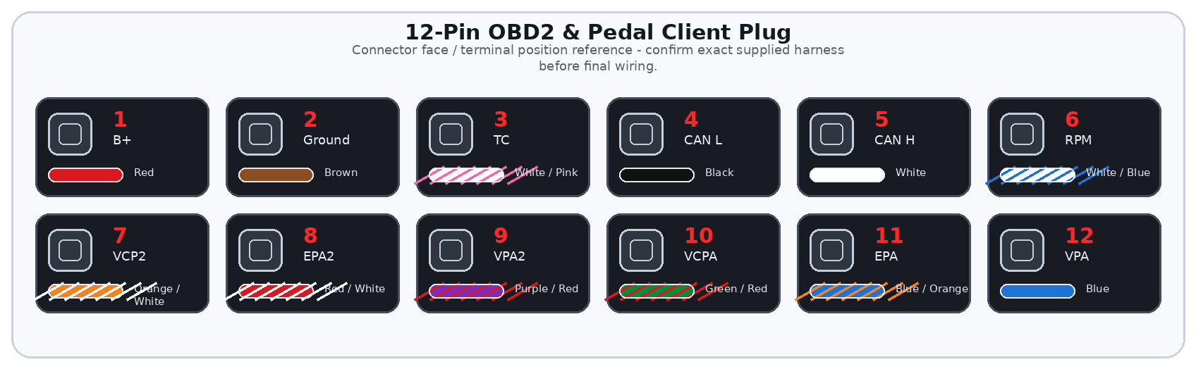
Overview
The 12-pin OBD2 and throttle pedal extension client plug combines diagnostic connector circuits and electronic accelerator pedal extension circuits into one serviceable client plug.
The OBD2/DLC3 portion provides power, ground, TC, CAN H, CAN L, and RPM. The pedal extension portion provides the six pedal sensor reference, ground, and signal circuits used by supported drive-by-wire applications.
Important
This guide covers the 12-pin client plug used for OBD2/DLC3 diagnostic wiring and accelerator pedal extension wiring on supported Lexus V8 standalone harness builds. It is not a complete chassis harness guide.
General Information Notice
This document is provided for general information and customer reference only. Final wiring must be verified against the exact harness supplied and the vehicle-side circuit being connected.
Quick Start: Critical Connections
| Function Group | Circuit / Pin | Wire(s) | Customer Connection |
|---|---|---|---|
| B+ | Client Pin 1 | Red | OBD2 Pin 16 – permanent fused +12V. |
| Ground | Client Pin 2 | Brown | OBD2 Pins 4 and 5 – diagnostic connector ground. |
| TC | Client Pin 3 | White / Pink | OBD2 Pin 13 – Toyota diagnostic/test terminal. |
| CAN L | Client Pin 4 | Black | OBD2 Pin 14 – CAN Low. |
| CAN H | Client Pin 5 | White | OBD2 Pin 6 – CAN High. |
| RPM | Client Pin 6 | White / Blue | OBD2 Pin 9 – engine speed signal. |
| Pedal Sensor 2 | Pins 7-9 | Orange/White; Red/White; Purple/Red | Pedal pins 1-3: VCP2, EPA2, VPA2. |
| Pedal Sensor 1 | Pins 10-12 | Green/Red; Blue/Orange; Blue | Pedal pins 4-6: VCPA, EPA, VPA. |
Wire Color / Tracer Reference
Stripe/tracer colors are shown as diagonal bands on the wire. The first color is the base wire color. The second color is the stripe/tracer color.
Full Pinout Reference
| Pin | Wire Visual | Circuit / Function | Signal Type | Notes |
|---|---|---|---|---|
| Pin 1 | Red | B+ | Permanent +12V supply | Connect to OBD2 Pin 16. Use proper fuse protection. |
| Pin 2 | Brown | Ground | Ground supply | Connect to OBD2 Pins 4 and 5. Split cleanly to both diagnostic connector grounds. |
| Pin 3 | White / Pink | TC | Diagnostic/test terminal | Connect to OBD2 Pin 13. Keep isolated from B+, ground, CAN, RPM, and pedal circuits. |
| Pin 4 | Black | CAN L | CAN Low communication | Connect to OBD2 Pin 14. Must remain paired correctly with CAN H. |
| Pin 5 | White | CAN H | CAN High communication | Connect to OBD2 Pin 6. Do not reverse CAN H and CAN L. |
| Pin 6 | White / Blue | RPM | Engine speed signal | Connect to OBD2 Pin 9. Do not connect to high-current devices. |
| Pin 7 | Orange / White | VCP2 | Accelerator pedal reference | Connect to accelerator pedal 1×6 Pin 1. Sensor 2 reference supply. |
| Pin 8 | Red / White | EPA2 | Accelerator pedal ground | Connect to accelerator pedal 1×6 Pin 2. Sensor 2 ground. |
| Pin 9 | Purple / Red | VPA2 | Accelerator pedal signal | Connect to accelerator pedal 1×6 Pin 3. Sensor 2 signal. Do not power or ground. |
| Pin 10 | Green / Red | VCPA | Accelerator pedal reference | Connect to accelerator pedal 1×6 Pin 4. Sensor 1 reference supply. |
| Pin 11 | Blue / Orange | EPA | Accelerator pedal ground | Connect to accelerator pedal 1×6 Pin 5. Sensor 1 ground. |
| Pin 12 | Blue | VPA | Accelerator pedal signal | Connect to accelerator pedal 1×6 Pin 6. Sensor 1 signal. Do not power or ground. |
Detailed Circuit Notes
OBD2/CAN circuits
- Verify OBD2 Pin 16 power and Pins 4/5 ground before plugging in a scan tool.
- CAN H must connect to Pin 6 and CAN L to Pin 14. Reversed CAN wires can stop scan tool communication.
- TC must remain isolated except when a diagnostic procedure calls for it.
Pedal circuits
- Pedal reference, ground, and signal wires are sensor circuits and must not be used for power or loads.
- Keep VCP2 separate from VCPA and EPA2 separate from EPA.
- Route the pedal extension away from sharp edges, pedals, steering shafts, and heat.
First Test Checklist
| Item | Check |
|---|---|
| OBD2 power | Pin 16 has fused +12V and Pins 4/5 ground. |
| CAN | CAN H and CAN L are correct and not reversed. |
| Pedal continuity | All six pedal circuits have continuity to the correct pedal pins. |
| Pedal isolation | No pedal signal, reference, or ground circuit is shorted to another circuit. |
Troubleshooting Quick Reference
| Symptom | Items to Check |
|---|---|
| No CAN communication | Check OBD2 power/ground and CAN H/L orientation. |
| Pedal fault codes | Check pedal pin order, sensor 1/sensor 2 circuits, and connector orientation. |
| RPM missing at OBD2 | Check White/Blue RPM wire to OBD2 Pin 9 and signal compatibility. |