 Lexus V8 Engines LLC
4-Pin Cruise Control Client Plug Guide
Cruise Control Brake Switch, Lever, and Indicator Reference
Vehicle-side cruise control client plug wiring
Build-Specific Confirmation
Confirm brake-switch operation, cruise lever compatibility, indicator polarity, terminal locations, and exact harness labels before final installation. Brake switch wiring is safety-critical because cruise must cancel immediately when the brake pedal is applied.
Connector Visuals
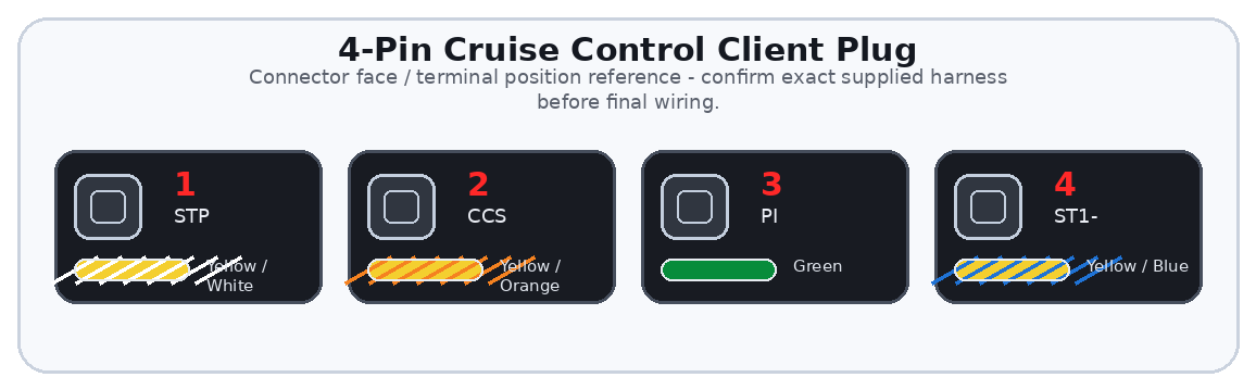
Overview
The 4-pin cruise control client plug separates the cruise control wiring from the main engine and transmission client plugs. This makes the vehicle-side cruise circuits easier to test and service.
The plug provides two brake switch inputs, the cruise control lever signal, and a cruise indicator light circuit where applicable.
Important
This guide covers the vehicle-side 4-pin cruise control client plug only. The standalone harness provides the cruise-related interface circuits, but the installer must still wire the brake switch, cruise lever, and dash indicator correctly for the receiving vehicle.
General Information Notice
This document is provided for general information and customer reference only. Final wiring must be verified against the exact harness supplied and the vehicle-side circuit being connected.
Quick Start: Critical Connections
| Function Group | Circuit / Pin | Wire(s) | Customer Connection |
|---|---|---|---|
| Brake Switch N/O | STP | Pin 1 | Connect to the normally open brake switch circuit. This changes state when the brake pedal is applied. |
| Cruise Lever | CCS | Pin 2 | Connect to the compatible cruise control lever/switch signal circuit. |
| Cruise Indicator | PI | Pin 3 | Connect to the dash cruise indicator light where applicable. |
| Brake Switch N/C | ST1- | Pin 4 | Connect to the normally closed brake switch circuit. This should change state opposite STP. |
Wire Color / Tracer Reference
Stripe/tracer colors are shown as diagonal bands on the wire. The first color is the base wire color. The second color is the stripe/tracer color.
Full Pinout Reference
| Pin | Wire Visual | Circuit / Function | Signal Type | Notes |
|---|---|---|---|---|
| Pin 1 | Yellow / White | STP | Brake switch normally open input | Connect to the normally open brake switch circuit. This is the brake-applied signal used by ECU/cruise logic. |
| Pin 2 | Yellow / Orange | CCS | Cruise control lever signal | Connect to the cruise lever/switch signal. Confirm lever type and resistor/switch strategy before connecting. |
| Pin 3 | Green | PI | Cruise control indicator light | Connect to the cruise dash indicator light where applicable. Low-current indicator only. |
| Pin 4 | Yellow / Blue | ST1- | Brake switch normally closed input | Used as the second brake switch/cruise cancel confirmation input. Must change state opposite STP. |
Detailed Circuit Notes
Brake switch circuits
- Identify the normally open and normally closed brake switch circuits with a meter before connecting.
- With the brake released, one brake circuit should be closed while the other is open. When the brake is pressed, they should swap state.
- Do not join STP and ST1- together. They are separate safety and logic inputs.
Cruise lever signal
- Confirm the cruise lever is compatible with the ECU/cruise strategy being used.
- Do not apply direct power to CCS unless the build-specific wiring diagram calls for it.
- Verify ON/OFF, SET/COAST, RES/ACC, and CANCEL commands with scan data or electrical testing when possible.
Indicator light
- Confirm whether the cluster expects ground-side control or positive feed.
- Use a low-current lamp or LED with proper current limiting.
- Do not use the PI circuit to power relays or high-current lights.
First Test Checklist
| Item | Check |
|---|---|
| Brake release | STP and ST1- show opposite states. |
| Brake applied | STP and ST1- swap state cleanly. |
| Cruise lever | Commands are visible with scan data or verified electrically. |
| Indicator | PI operates the cruise indicator with correct polarity. |
Troubleshooting Quick Reference
| Symptom | Items to Check |
|---|---|
| Cruise will not set | Check STP/ST1- states, CCS lever compatibility, and brake light operation. |
| Cruise cancels immediately | ST1- or STP may be wired incorrectly or showing the wrong state. |
| Indicator does not light | Check PI polarity, lamp feed, LED resistor, and cluster wiring. |