 Lexus V8 Engines LLC
3UZ 9-Pin 6-Speed Transmission Client Plug Guide
6-Speed Automatic Transmission Vehicle-Side Reference
3UZ 6-speed automatic standalone transmission interface
Build-Specific Confirmation
Always confirm connector orientation, terminal location, wire color, circuit function, signal direction, polarity, fuse protection, and build-specific instructions before final installation. Do not wire by color alone.
Connector Visuals
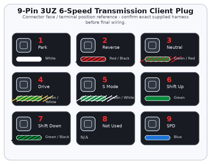
Overview
The 9-pin plug provides the main vehicle-side connections used for shifter range outputs, sport/manual mode selection, manual shift up/down requests, and vehicle speed signal integration.
Correct range and speed wiring are important for gear selection, torque converter lockup, diagnostic logic, and safe vehicle operation.
Important
This guide covers the vehicle-side 9-pin 3UZ 6-speed automatic transmission client plug. The standalone harness is an engine and transmission control system, not a full chassis or body harness.
General Information Notice
This document is provided for general information and customer reference only. Final wiring must be verified against the exact harness supplied and the vehicle-side circuit being connected.
Quick Start: Critical Connections
| Function Group | Circuit / Pin | Wire(s) | Customer Connection |
|---|---|---|---|
| Range Position Outputs | P / R / N / D | Pins 1-4 | 12V range outputs for shifter or vehicle-side range logic. |
| Sport / Manual Mode | S | Pin 5 | Input requiring 12V when S mode is requested. |
| Manual Shift Requests | Shift Up / Shift Down | Pins 6-7 | Momentary ground-input request circuits. |
| Vehicle Speed | SPD | Pin 9 | Compatible speed signal input from cluster or vehicle speed source. |
Wire Color / Tracer Reference
Stripe/tracer colors are shown as diagonal bands on the wire. The first color is the base wire color. The second color is the stripe/tracer color.
Full Pinout Reference
| Pin | Wire Visual | Circuit / Function | Signal Type | Notes |
|---|---|---|---|---|
| Pin 1 | White | Park | 12V range output | Park range output for shifter/vehicle-side range logic. Verify active only in Park. |
| Pin 2 | Red / Black | Reverse | 12V range output | Reverse range output. Do not use to power reverse lamps unless the vehicle circuit is designed for it. |
| Pin 3 | Green / Red | Neutral | 12V range output | Neutral range output for ECU/shifter logic and neutral safety strategy where applicable. |
| Pin 4 | Green / Yellow | Drive | 12V range output | Drive range output for normal 6-speed automatic operation. |
| Pin 5 | Green / White | S | 12V input | Sport/manual mode request input. Feed 12V only when S mode is selected. |
| Pin 6 | Green | Shift Up | Ground-input request | Momentary shift-up request. Ground this circuit only during the request. |
| Pin 7 | Green / Black | Shift Down | Ground-input request | Momentary shift-down request. Ground this circuit only during the request. |
| Pin 8 | N/A | Not Used | No customer connection | Leave unused unless build-specific instructions say otherwise. |
| Pin 9 | Blue | SPD | Speed from cluster input | Provide compatible speed signal to ECU/transmission logic. |
Detailed Circuit Notes
Range outputs
- Verify each range output is active only in its matching shifter position.
- Do not use range output wires as general power feeds.
- Reverse lamps normally require a fused chassis-side circuit or relay strategy.
Manual mode
- Do not permanently power S mode unless the build specifically requires it.
- Shift Up and Shift Down should use momentary switch contacts to ground.
- Verify manual shift requests with scan data or electrical testing before road testing.
Speed signal
- Confirm source, signal type, and pulse rate.
- Missing or incompatible speed signal can cause shift complaints, lockup issues, or DTCs.
First Test Checklist
| Item | Check |
|---|---|
| PRND | Park, Reverse, Neutral, and Drive outputs match shifter position. |
| S Mode | S mode input changes only when requested. |
| Shift Up/Down | Momentary ground inputs operate correctly. |
| SPD | Speed signal is present and compatible. |
Troubleshooting Quick Reference
| Symptom | Items to Check |
|---|---|
| No shift or wrong gear indication | Check range output wiring and shifter position logic. |
| Manual shift does not work | Check S mode input and Shift Up/Down ground request circuits. |
| No lockup or speed-related DTC | Check SPD source, pulse rate, and signal conditioner if used. |