Adjustable A/C Idle-Up System for Lexus / Toyota UZ Engine Swaps
Workshop installation guide · Metered bypass air · Adjustable idle compensation
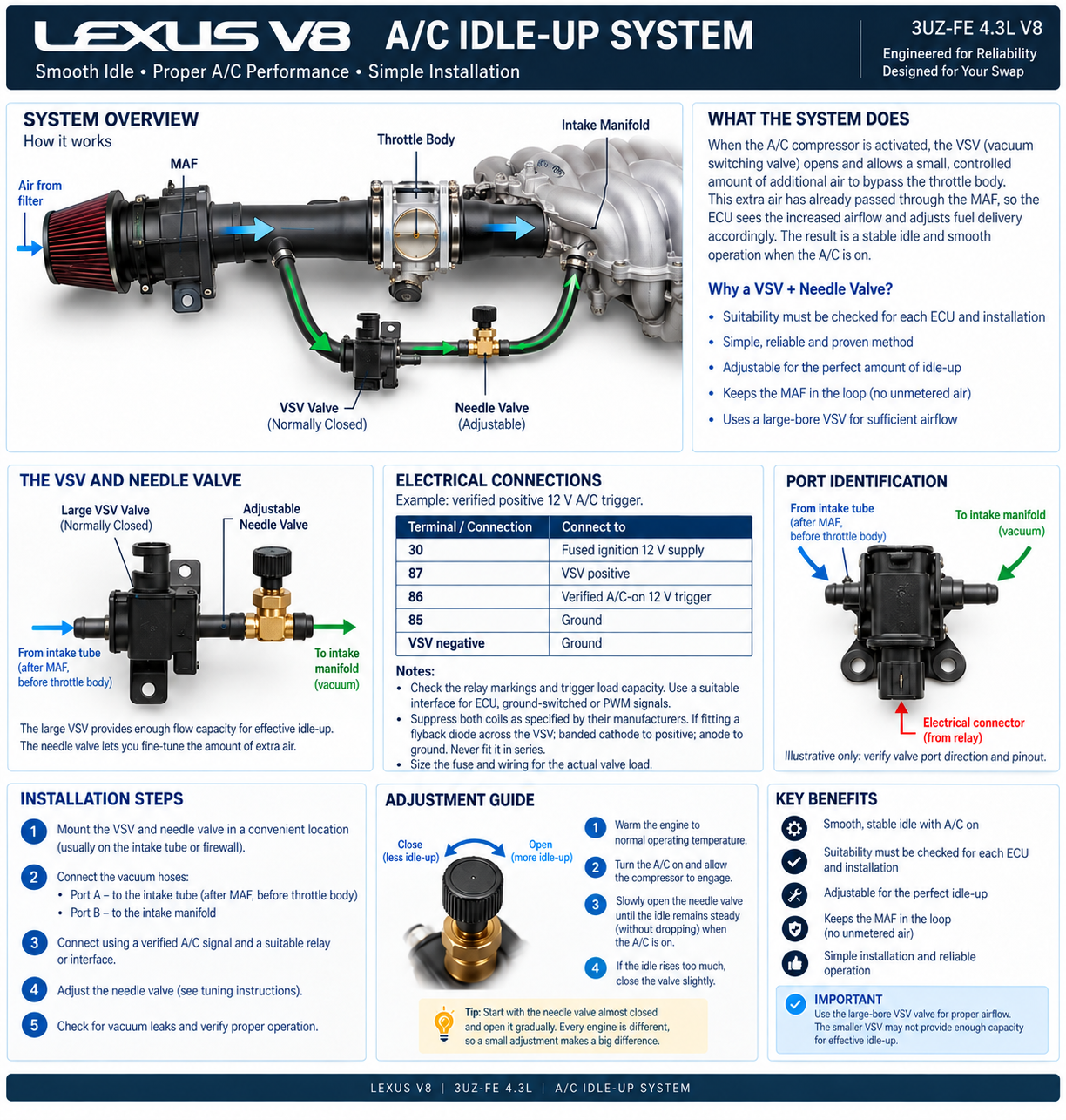
When an air-conditioning compressor engages, it places an additional mechanical load on the engine. In the original Lexus or Toyota vehicle, the engine-management system normally compensates for this load by increasing idle torque or idle speed.
During an engine swap, however, the original Lexus A/C amplifier, multiplex communication system, CAN communication or other supporting electronics may no longer be present. Different UZ ECU generations also use different methods to determine when the A/C compressor has been requested.
For this reason, Lexus V8 Engines uses a simple adjustable bypass-air system to provide reliable A/C idle-up without depending on the original vehicle’s complete A/C communication system.
The system uses:
- A normally-closed Vacuum Switching Valve (VSV)
- An adjustable needle valve
- A metered air supply taken after the MAF
- A connection to intake-manifold vacuum
- An electrical trigger that operates whenever the A/C compressor is activated
The result is a simple, adjustable system that can be used across a wide range of UZ engine swaps.
Why A/C Idle-Up Is Needed
When the compressor clutch engages, the compressor immediately adds load to the engine.
If the engine is idling, this additional load can cause:
- Idle speed to drop
- Rough or unstable idle
- Engine vibration
- Stalling in severe cases
- Excessive idle drop when an automatic transmission is also in Drive
The purpose of the idle-up system is not to make the engine idle unnecessarily high.
Its purpose is to provide just enough additional airflow to compensate for the compressor load and maintain a smooth, stable idle.
How the System Works
The system creates a controlled air bypass around the throttle body.
Under normal conditions, all engine airflow passes through the MAF and then through the throttle body.
With the A/C idle-up system fitted, a small additional air path is created from the intake tube to the intake manifold.
The air path is:
Air filter → MAF → Intake tube → Throttle body → Intake manifold
The idle-up bypass is:
Intake tube after MAF / before throttle body → VSV → Needle valve → Intake manifold
When the A/C compressor is OFF:
- The VSV is not energized.
- The VSV remains closed.
- No additional bypass air enters the engine.
- The engine idles normally.
When the A/C compressor is ON:
- The VSV is energized.
- The VSV opens.
- A controlled amount of air bypasses the throttle body.
- The additional air enters the intake manifold.
- Engine idle speed increases slightly.
- The extra airflow compensates for compressor load.
Why the Air Must Be Taken After the MAF
This is the most important part of the installation.
The bypass air must be taken from the intake tube after the Mass Air Flow meter and before the throttle body.
This means the additional air has already passed through the MAF before it enters the engine.
The ECU therefore knows that the extra air is entering the engine and can provide the correct amount of fuel.
Correct:
Air filter → MAF → Idle-up air take-off → Throttle body
Incorrect:
Idle-up air taken from before the MAF
If the bypass air is taken before the MAF, the ECU will not measure it.
That would create unmetered air entering the intake manifold, effectively creating a vacuum leak.
This can cause:
- Lean fuel trims
- Rough idle
- Poor throttle response
- Incorrect air/fuel ratio
- Misfire codes
- Unstable engine operation
For this reason, the idle-up bypass must always use metered air.
Selecting the Correct VSV
A normally-closed Toyota or Lexus Vacuum Switching Valve should be used.
We recommend using a VSV with the larger hose connections.
There are smaller and larger VSV valves used throughout Toyota and Lexus applications.
For A/C idle-up, the larger version is preferred because it provides greater airflow capacity.
Do not worry if the larger valve flows more air than the engine requires.
The amount of actual idle-up is controlled by the adjustable needle valve.
Using a larger VSV combined with a needle valve gives a much wider adjustment range than using a small VSV that may not flow enough air.
Verify the valve part number, port flow direction, 12 V rating, duty cycle and connector polarity. Larger hose connections alone do not prove that a valve is suitable. Do not use a three-port valve without confirming its internal flow paths.
The VSV must be normally closed.
This means that when no electrical power is applied, the valve blocks the bypass airflow.
What the Needle Valve Does
The needle valve is used to fine-tune the amount of idle-up.
It should normally be installed between the VSV and the intake manifold.
The layout is:
Intake tube → VSV → Needle valve → Intake manifold
Opening the needle valve allows more bypass airflow.
More airflow = more idle-up.
Closing the needle valve reduces bypass airflow.
Less airflow = less idle-up.
This makes the system adjustable for:
- Different UZ engines
- Different compressors
- Different pulley loads
- Manual or automatic transmissions
- Different vehicle installations
Each vehicle can therefore be adjusted individually.
Recommended Vacuum Plumbing
The recommended hose routing is:
Port 1:
Connect to the intake tube after the MAF and before the throttle body.
Port 2:
Connect through the adjustable needle valve to the intake manifold.
Use vacuum hose suitable for engine-bay temperatures.
All hose connections must be airtight.
Any uncontrolled vacuum leak can affect fuel trims and idle quality.
Electrical Operation
The VSV should be energized whenever the A/C compressor is operating.
On a conventional magnetic-clutch compressor, a verified compressor-on signal can trigger a suitable relay or interface. Check the vehicle wiring diagram and measure the signal before connecting anything. Do not bypass the original pressure switches, temperature controls or compressor safety cut-outs.
The basic sequence is:
A/C requested
↓
Compressor activated
↓
VSV activated
↓
Bypass air enters intake manifold
↓
Idle speed increases
↓
Compressor load is compensated
Recommended Relay Wiring
We recommend operating the VSV through a relay rather than placing additional electrical load directly onto an ECU output.
A typical arrangement is:
A/C compressor trigger → Relay coil
Fused ignition 12 V → Relay contact → VSV
VSV → Ground
When the compressor is commanded on, the relay energizes and supplies power to the VSV.
The relay contacts keep the VSV load off the trigger circuit, but the relay coil still draws current from that trigger. Confirm the signal polarity, available current and suppression requirements before connecting it. Do not assume an ECU output can drive a relay coil. Use a suitable interface for ground-switched, PWM, multiplexed or low-current control signals.
Suppress both the relay coil and the VSV coil as specified by their manufacturers. If a flyback diode is appropriate and the VSV has no internal suppression, connect it in parallel across the VSV coil: banded cathode to VSV positive and anode to VSV ground. Never fit it in series. Verify the diode rating and observe polarity; a reversed diode can short the supply.
This helps protect the switching circuit from voltage spikes when the VSV is switched off.
Example: verified positive 12 V A/C trigger
This example is for a conventional normally-open four-pin relay. Follow the markings and datasheet for the actual relay. It is not a universal ECU pinout.
| Terminal / connection | Connect to |
|---|---|
| 30 | Fused ignition 12 V supply |
| 87 | VSV positive |
| 86 | Verified A/C-on positive 12 V trigger with sufficient coil-current capacity |
| 85 | Ground |
| VSV negative | Ground |
Place the fuse close to the supply take-off and size it to protect the wire and actual valve load. Relay contact capacity is not the fuse rating. Use automotive-rated wiring, sealed connections and suitable coil suppression. A five-pin relay’s normally-closed terminal 87a is not used in this example.
Terminal-reference example: HELLA normally-open relay pin designations. Always verify your own part.
Magnetic-Clutch Compressors
This system is easiest to use with a conventional magnetic-clutch compressor.
When the compressor clutch is activated, the same command can also activate the VSV relay.
This gives a direct relationship between compressor load and idle-up.
Compressor ON = Idle-up ON
Compressor OFF = Idle-up OFF
Variable-Displacement Compressors
Some later Lexus systems use a variable-displacement or variable-stroke compressor instead of a traditional magnetic clutch.
These compressors may not have a simple clutch-power wire that switches on and off.
In these applications, the VSV should be triggered from an appropriate A/C request or compressor-operation signal.
The principle remains the same:
Whenever compressor load is applied to the engine, the VSV should open and provide the required additional bypass airflow.
Initial Adjustment Procedure
The engine should already be running correctly before adjusting the idle-up system. Work in a ventilated area, secure the vehicle, and keep hands, tools, hoses and wiring clear of belts, fans and hot exhaust components.
Do not use the idle-up valve to compensate for an unrelated engine problem.
Before adjustment, confirm:
- No vacuum leaks
- Correct MAF installation
- Correct fuel pressure
- Correct throttle-body operation
- Stable normal idle
- Engine fully warmed up
Then adjust the system as follows:
- Bring the engine completely up to normal operating temperature.
- Switch the A/C compressor OFF.
- Confirm that the engine has a stable normal idle.
- Close the needle valve almost completely.
- Switch the A/C compressor ON.
- Observe the change in engine speed.
- Slowly open the needle valve.
- Continue opening it until the compressor can engage without causing a significant drop in engine speed.
- Cycle the A/C compressor ON and OFF several times.
- Fine-tune the needle valve until the transition is smooth.
The objective is to maintain a stable idle, not to create an excessively high idle.
Automatic Transmission Vehicles
If the vehicle has an automatic transmission, the system should also be tested with the transmission in Drive.
With the engine fully warm:
- Use a clear, level test area with the parking brake applied and wheels chocked.
- Have a competent driver remain in the seat and hold the service brake firmly before selecting Drive.
- Switch the A/C compressor ON and observe idle quality.
- Return to Park, switch the engine off and make any physical adjustment safely; repeat the check as needed. Never work in front of or behind a vehicle left in gear.
Automatic vehicles place additional load on the engine at idle, so the final adjustment should be made under realistic operating conditions.
Manual Transmission Vehicles
For manual vehicles, adjustment can normally be completed with the transmission in Neutral.
The system should still be tested under different electrical and engine loads to ensure the idle remains stable.
Why We Prefer This Method for Engine Swaps
Different Lexus and Toyota ECU generations handle A/C idle compensation differently.
Depending on the ECU, the original vehicle may use:
- A direct A/C request input
- An A/C amplifier
- MPX / BEAN communication
- CAN communication
- ECU-controlled compressor logic
- Variable-displacement compressor control
Recreating the complete original A/C communication system for every swap can become unnecessarily complicated.
The adjustable VSV system can avoid some of that complication on a suitable installation. It does not replace compressor protection or guarantee compatibility with every ECU. Electronic idle control may counteract added airflow; validate the actual response and check for fault codes before relying on the system.
It provides a simple mechanical airflow solution that is independent of the original Lexus body electronics.
Advantages include:
- Can suit multiple ECU generations, subject to installation-specific checks
- Does not rely on original Lexus body modules
- Does not require CAN or MPX emulation
- Simple to diagnose
- Simple to install
- Fully adjustable
- Uses metered air
- Maintains correct MAF operation
- Can be used with manual or automatic swaps
- Easy to service in the future
Important Installation Rules
The VSV must be normally closed.
The VSV air supply must come from after the MAF.
The VSV air supply must come from before the throttle body.
The outlet must connect to the intake manifold.
Use the larger-port VSV where possible.
Use a needle valve to control airflow.
Do not introduce unmetered air.
Do not connect the VSV directly to an ECU output unless the output has been confirmed suitable.
Use a relay where required.
Check all hoses carefully for leaks.
Do not use the system to hide an existing engine fault.
Simple System Summary
A/C OFF:
VSV closed
↓
No bypass air
↓
Normal idle
A/C ON:
Compressor activated
↓
VSV opens
↓
Metered air bypasses throttle body
↓
Additional air enters intake manifold
↓
Engine idle increases
↓
Compressor load is compensated
Recommended Installation Layout
Air path:
Air Filter
↓
MAF
↓
Intake Tube
↓
Throttle Body
↓
Intake Manifold
Idle-Up Bypass:
Intake Tube after MAF
↓
Large Normally-Closed VSV
↓
Adjustable Needle Valve
↓
Intake Manifold
Electrical:
A/C Compressor Command
↓
Idle-Up Relay
↓
VSV
↓
Ground
Final Result
Once suitability has been confirmed and the system is correctly installed and adjusted, the intended result is a smooth, predictable idle whenever the A/C compressor is operating.
Because the bypass airflow has already passed through the MAF, the ECU continues to calculate engine airflow correctly.
The needle valve allows the installer to precisely match the amount of idle-up to the actual compressor load.
This makes the system a simple, reliable and highly adjustable solution for A/C idle compensation on Lexus and Toyota UZ engine swaps.
Lexus V8 Engines LLC
www.lexusv8.com
305 619 5355