LEXUS V8 Engines LLC

Technical Training Module 04

Analog and Digital Meters

A meter-use page covering analog and digital meters, range selection, impedance, polarity, continuity, and safe probing.

voltagecurrentresistancegroundrelaybatterystartervoltage drop
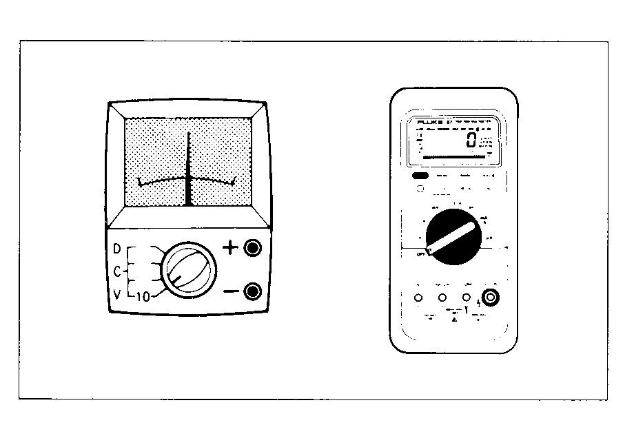
Analog and Digital Meters training diagram for Lexus V8 technical checks

What This Lesson Teaches

Objective 01

Choose the correct meter function and range before connecting.

Objective 02

Understand when a digital meter can mislead because the circuit is unloaded.

Objective 03

Use continuity and resistance tests without back-feeding an ECU.

Objective 04

Protect meter fuses by avoiding current tests across a power source.

How The System Works

A digital multimeter measures voltage by comparing two points while drawing very little current; current mode places the meter in series; resistance and continuity modes use the meter’s internal source and must only be used on a de-energized, isolated circuit. On a Toyota/Lexus OEM-ECU swap, most live checks are DC-voltage or voltage-drop tests made with the connector attached and the circuit in its commanded state.

High input impedance can display induced or back-fed voltage on an unloaded wire, so a voltage reading alone does not prove current capacity. Compare the suspect feed and ground with battery-post voltage under normal load, and use an oscilloscope for rapidly changing signals. Use a factory-approved low-current load only on conventional power or ground circuits; do not load a five-volt reference, sensor signal, CAN circuit or ECU driver unless the service procedure explicitly permits it.

Step By Step Test Procedure

Prepare the meter and specification

  • Identify the exact circuit and expected operating state; inspect the leads, meter fuse, input jacks and selected function.
Establish a reference

  • Record battery-post voltage in the relevant key state and verify the chosen meter ground before comparing a downstream reading.

Back-probe the live circuit

  • Check the feed, reference, signal or control terminal while the ECU or component operates. Never force a probe into or spread a terminal.

Measure voltage drop

  • With current flowing, test the positive side and ground side separately and divide an excessive drop into smaller harness sections.

Capture intermittent behaviour

  • Move the harness while watching the meter or scope. Treat an unloaded ghost voltage as unproven until an approved loaded test confirms it.

Use resistance mode safely

  • Switch power off and disconnect the modules required by the diagram; verify lead resistance, test the isolated path and reconnect everything before the final live test.

Expected Readings And What They Mean

CheckExpected EvidenceDiagnostic Meaning
Battery post versus ECU/component feedFeed remains within the factory voltage-drop allowance for that operating stateA larger difference identifies loss on the supply path.
Loaded ground pathDrop remains within factory specification and close to zeroExcess drop identifies resistance between the circuit ground and battery negative.
Five-volt reference or sensor signalStable and within the exact ECU/component specificationA collapsed or biased value requires branch, sensor and harness isolation before ECU diagnosis.
Isolated resistance or continuityStable and within factory specification with power removed and affected modules disconnectedOpen, unstable or unintended continuity indicates a conductor, terminal or cross-circuit fault.

Use This Carefully

This training page is an independent Lexus V8 Engines LLC rewrite for educational and diagnostic support. Lexus V8 Engines LLC is not affiliated with or endorsed by Toyota Motor Corporation. Always use the correct factory service information for final specifications, safety procedures, and vehicle-specific wiring.