Technical Training Module 02
Electrical Circuits
A practical guide to series, parallel, series-parallel, open, shorted, grounded, and voltage-drop circuit testing.
voltagecurrentresistancegroundrelaybatteryalternatorvoltage drop
What This Lesson Teaches
Objective 01
Read the circuit path from source to ground without skipping connectors.
Objective 02
Predict what voltage should be present before placing the meter lead.
Objective 03
Diagnose opens, shorts, grounds, and high-resistance faults using the correct test.
Objective 04
Use voltage-drop testing to prove wiring and connectors under load.
How The System Works
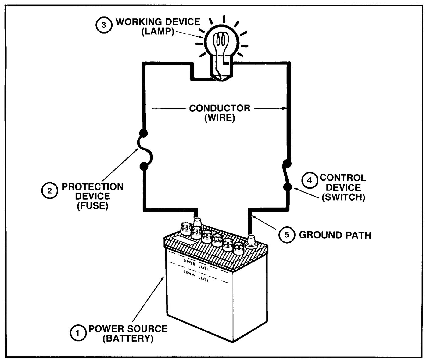
An OEM-ECU swap circuit may pass through the battery or junction block, a fuse, relay contacts, a splice, conversion-harness connectors, the load, and one or more grounds. The ECU may monitor an input, switch a relay or solenoid on the low side, or in some variants command another module. The exact Toyota/Lexus wiring diagram determines which path applies; do not infer it from wire colour or connector shape.
An open interrupts the intended path, a short to ground or power creates an unintended path, and excessive resistance steals voltage only when current flows. Diagnose in the commanded state by comparing source and load voltages and moving through the diagram between the last correct point and first incorrect point. Use a current-limited method for a suspected short so repeated fuse replacement does not damage the harness.
Step By Step Test Procedure
01Map the circuit
- Confirm the engine, ECU and harness variant, then mark the source, fuse, relay coil and contacts, splices, connectors, load, return path and ECU terminal on the matching diagram.
02Capture the fault condition
- Stabilize battery voltage and reproduce the complaint safely. Record the ignition state, ECU command and any relevant diagnostic trouble code or scan-data state.
03Test protection and switching
- With the circuit commanded on, measure both sides of the fuse and both sides of the relay contacts relative to battery negative. Compare each reading with battery-post voltage.
04Locate an open
- Trace point-by-point or divide the circuit in half. The fault lies between the last point with the expected state and the first point without it.
05Find resistance under load
- Voltage-drop the power and ground sides separately while the load operates. Subdivide the side with excessive loss until the faulty joint is isolated.
06Isolate a short safely
- Remove power and disconnect branches in diagram order. Use a fused, current-limited substitute only where the factory procedure permits, repair the affected branch, fit the correct fuse and repeat the original test.
Expected Readings And What They Mean
| Check | Expected Evidence | Diagnostic Meaning |
|---|
| Fuse input and output under command | The specified supply is present on both sides of a serviceable fuse | Supply on only one side identifies an open fuse or terminal connection. |
|---|
| Relay contact path under load | Input and output remain within the factory voltage-drop allowance while the relay is commanded | Excessive loss with a valid coil command points to contacts, sockets or connecting terminals. |
|---|
| Open-circuit trace | The expected state remains present up to the last good test point | The break is between that point and the first point where the expected state disappears. |
|---|
| Short-circuit branch isolation | Current draw falls to the normal range when the affected branch is disconnected using an approved current-limited method | The short is in that branch; inspect rub points, splices and connector terminals before repowering. |
|---|
Use This Carefully
This training page is an independent Lexus V8 Engines LLC rewrite for educational and diagnostic support. Lexus V8 Engines LLC is not affiliated with or endorsed by Toyota Motor Corporation. Always use the correct factory service information for final specifications, safety procedures, and vehicle-specific wiring.