Technical Training Module 40

Ignition: Electronic Spark Advance

Ignition: Electronic Spark Advance for spark generation, ECU ignition commands, igniters, coils, distributor systems, feedback, and timing control.
This page is written as a workshop training guide: learn the system, set up the test correctly, prove the circuit, interpret the result, and record the repair.

voltagesensorECUinjectorignitionoxygenknockshift
Electronic Spark Advance training diagram for Lexus V8 technical checks

What This Lesson Teaches

Objective 01

Understand what the system is meant to do before testing it.

Objective 02

Identify power, ground, input, output, and load points on the wiring diagram.

Objective 03

Use the correct meter or scope test instead of guessing at components.

Objective 04

Separate a wiring fault from a sensor, actuator, ECU, or mechanical fault.

How The System Works

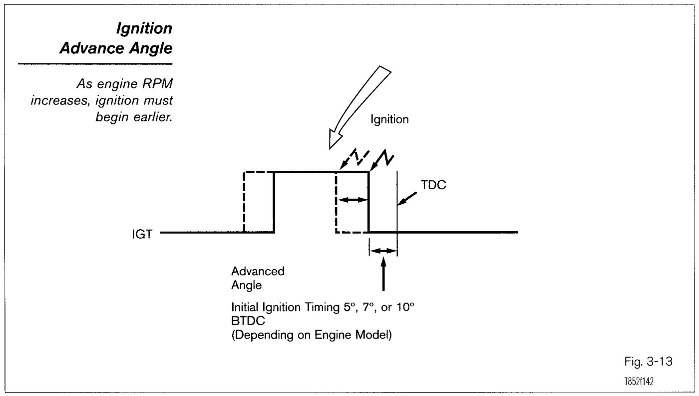
The ignition system must create a strong spark at the correct time. The ECU uses engine position, load, temperature, knock information, and programmed timing maps to command ignition events.

Toyota/Lexus systems may use distributor, distributorless, wasted-spark, or coil-on-plug layouts. Many use ECU ignition trigger signals and igniter feedback so the ECU knows whether spark control occurred.

A no-spark fault must separate power supply, ground, crank/cam input, ECU command, igniter, coil, secondary wiring, and mechanical timing.

Tools, Safety, And Setup

Required tools

  • Digital multimeter with min/max and duty-cycle or frequency capability
  • Incandescent test light for loaded power/ground checks where safe
  • Back-probe pins, fused jumper leads, and connector pinout references
  • Current clamp or low-amp probe for motors, pumps, solenoids, and alternator checks
  • Oscilloscope or graphing meter for crank, cam, MAF, ignition, and oxygen sensor signals

Safety and setup

  • Work with the vehicle secure, transmission in park or neutral, wheels chocked, and the ignition state deliberately controlled.
  • Do not pierce sealed wiring unless there is no better access point. Back-probe from the connector side where possible and reseal anything disturbed.
  • Use the correct meter range before connecting to a circuit. A meter on the wrong range can damage the meter, the ECU, or the circuit.
  • Load-test power and ground circuits. An unloaded circuit can show battery voltage and still fail when the component is asked to work.
  • Disconnect ECUs and sensitive modules before doing resistance checks unless the specific procedure says the circuit can remain connected.

Step By Step Test Procedure

01

No-spark diagnostic order

  1. Confirm ECU power, ECU ground, and engine speed signal while cranking.
  2. Check ignition coil or igniter power feed with the key on and while cranking.
  3. Check for ECU ignition command with a scope or suitable logic probe.
  4. Check igniter feedback where the system uses it.
  5. If command exists but spark is missing, test igniter, coil, secondary path, and mechanical distributor or cam timing.
02

Timing and advance check

  1. Confirm base timing method for the exact ECU and engine family.
  2. Put the ECU in the correct timing-check mode if required.
  3. Use a timing light to verify base timing and observe advance response.
  4. If timing is unstable, check crank/cam signals, distributor condition, wiring shielding, grounds, and ECU inputs.
03

Pre-test setup and pinout confirmation

  1. Confirm the exact engine, ECU, connector, and system variant before using a pin number or expected reading.
  2. Print or open the wiring diagram and mark the fuse, relay, ECU pins, connector joins, splices, and ground points.
  3. Inspect the connector physically before probing it. Look for pushed-back pins, spread terminals, corrosion, oil, water, heat marks, and broken locks.
  4. Stabilize battery voltage before testing. Low system voltage can create false sensor, ECU, starter, alternator, and transmission faults.
04

Loaded power and ground verification

  1. Test the feed and ground with the circuit connected and commanded on whenever it is safe to do so.
  2. Compare voltage at the component to voltage at the battery while the circuit is working.
  3. Voltage-drop the power side and ground side separately so the fault is not hidden by a good-looking open-circuit voltage reading.
  4. Do not move to sensor or ECU replacement until the supply and return path are proven under load.

Expected Readings And What They Mean

CheckNormal ResultWhat The Result Means
Ignition feedBattery voltage to coil/igniter when enabledLow feed voltage weakens spark and can mimic a bad coil.
Ignition commandPulsed ECU trigger signalUse a scope where possible. A meter may average the pulse and mislead.
Feedback signalSystem-specific confirmation pulseMissing feedback can stop injection or set ignition codes on some systems.

Fault Interpretation

Fault TypeTypical SymptomNext Test
Open circuitNo current flow, no voltage on the load side, or infinite resistance when isolated.Find the break by halving the circuit and testing from the source toward the load.
High resistanceVoltage appears correct with no load but drops when the circuit is asked to work.Use voltage-drop testing under load instead of relying on continuity alone.
Short to ground or powerFuse blows, signal is pinned high or low, or more than one circuit behaves incorrectly.Disconnect branches until the fault disappears, then inspect that branch closely.

Lexus V8 Swap Application

On a standalone Lexus V8 harness, always confirm the engine family, ECU part number, immobilizer state, transmission type, and body-interface requirements before applying a generic test result.

Many swap problems are caused by missing feeds, poor grounds, incorrect relay control, or connector damage rather than a failed ECU.

Record These Results

Battery voltage before testing

Record the exact result before moving to the next test. This makes the diagnosis repeatable and avoids guessing.

Connector pin numbers tested

Record the exact result before moving to the next test. This makes the diagnosis repeatable and avoids guessing.

Voltage, resistance, frequency, or waveform result

Record the exact result before moving to the next test. This makes the diagnosis repeatable and avoids guessing.

Whether the circuit was tested loaded or unloaded

Record the exact result before moving to the next test. This makes the diagnosis repeatable and avoids guessing.

Final fault location and repair made

Record the exact result before moving to the next test. This makes the diagnosis repeatable and avoids guessing.

Use This Carefully

This training page is an independent Lexus V8 Engines LLC rewrite for educational and diagnostic support. Lexus V8 Engines LLC is not affiliated with or endorsed by Toyota Motor Corporation. Always use the correct factory service information for final specifications, safety procedures, and vehicle-specific wiring.

When a harness or ECU is being sent to Lexus V8 Engines LLC, print or save the recorded readings and include the engine, ECU, transmission, immobilizer status, connector photos, and the exact symptom.