Confirm the matched input system
- Identify the donor engine, ECU part number, harness variant and sensor application using the matching factory diagram and specifications.
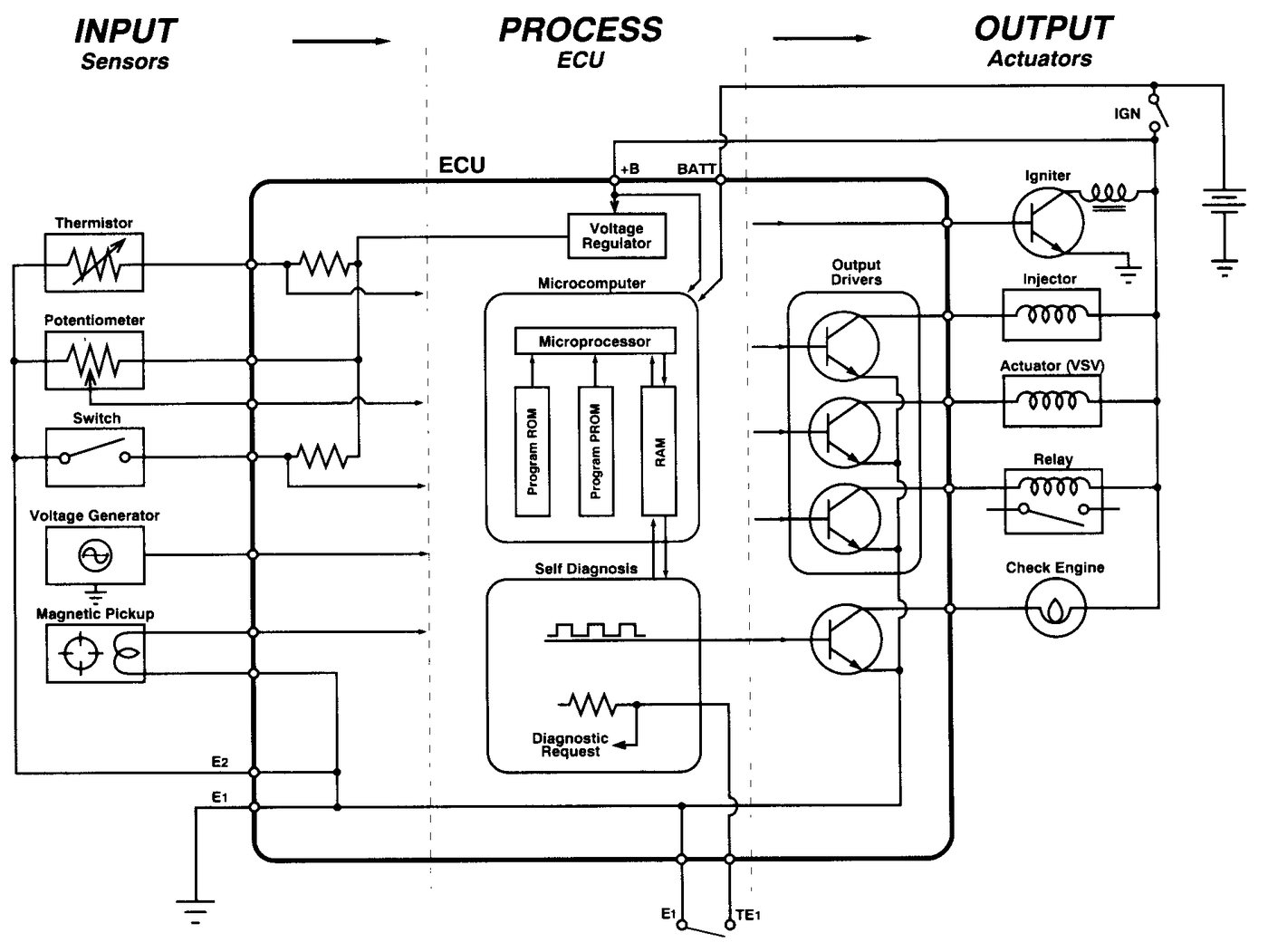
The Toyota or Lexus ECU learns operating conditions from electrical inputs rather than directly from the engine. Depending on the donor system, coolant and air temperature, airflow or pressure, throttle and pedal position, crank and cam position, and operating switches may produce variable-voltage, thermistor, frequency, magnetic, Hall-effect or switched signals. The ECU conditions these inputs and compares related signals before commanding fuel, ignition, throttle, idle and transmission functions.
In an OEM ECU swap, the ECU, sensors, calibration, connectors and sensor-ground arrangement must remain compatible. A connector that fits does not prove the signal type or pin arrangement is correct, and one shorted shared circuit can disturb several inputs. Compare scan data with the known physical condition first, then verify the signal at both the sensor and ECU; a plausible scan value alone does not prove the input is accurate.
| Check | Expected Evidence | Diagnostic Meaning |
|---|---|---|
| Known-condition scan data | Temperatures, throttle state, airflow or pressure and engine speed agree with the actual condition and donor strategy | An implausible value identifies the input family to test but does not by itself condemn the sensor. |
| Sensor supply and ground | The specified supply or reference remains stable with the sensor connected and the sensor-ground path remains sound under load | A disturbed shared supply or ground can make several good sensors report incorrectly. |
| Analog or switched input response | The signal changes smoothly or switches cleanly as the measured condition changes | A fixed value, dropout or unexpected transition indicates a sensor, terminal, wiring or compatibility fault. |
| Crank and cam evidence during cranking | Repeatable waveforms reach the ECU and engine-speed or synchronization data appears where supported | Missing or conflicting evidence can prevent injection or ignition even when ECU power is correct. |