Identify the signal method
- Confirm the engine, ECU, transmission and donor electrical variant. Locate the switch, source, intermediate connectors and expected signal type in the factory diagram.
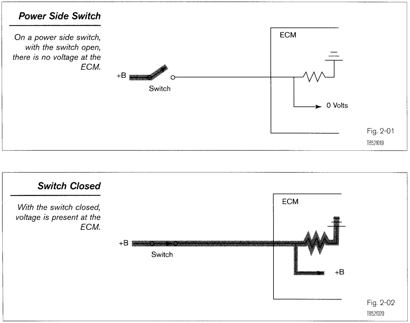
Mode sensors and switches report operating states such as start request, park or neutral, brake application, air-conditioning request and drive-mode selection. Depending on the Toyota or Lexus system, the ECU may expect a switched battery-voltage input, switched ground, resistance-coded state or a message from another control module. The correct factory diagram must define the signal type before it is tested or recreated in a swap harness.
During an OEM ECU swap, a missing, floating or inverted mode input can affect cranking authorization, idle control, ignition strategy and automatic-transmission operation without indicating an internal ECU failure. Diagnosis should prove the physical switch, its supply or ground, the complete harness path and the ECU’s interpreted state in that order.
| Check | Expected Evidence | Diagnostic Meaning |
|---|---|---|
| Start-request input | Electrical state and scan status change only while the key or start control requests cranking | No change points to a missing feed, incorrect logic, open circuit or absent network message. |
| Park/neutral or clutch status | Reported state agrees with actual selector or clutch position and changes only at intended positions | A fixed or incorrect state suggests switch adjustment, selector wiring, interface logic or circuit trouble. |
| Brake-switch input | ECU status changes promptly with pedal application and returns when the pedal is released | Disagreement can affect torque management, cruise cancellation, shift functions or idle behaviour where fitted. |
| A/C or drive-mode request | Requested mode appears at the ECU only when commanded and follows the signal method in the factory diagram | Valid switch output without ECU recognition indicates a harness, polarity, coding or module-interface mismatch. |