Identify the device and switching method
- Use the exact ECU and harness diagram to identify the load feed, driver terminal, low-side or high-side switching method, protective device and expected command conditions.
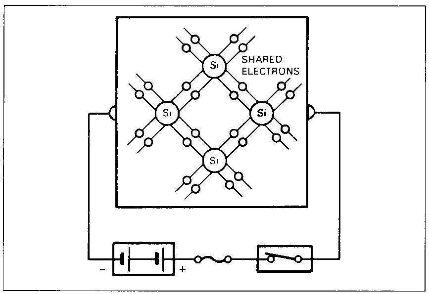
Toyota/Lexus ECUs use semiconductor devices to condition sensor inputs and control outputs. Diodes steer current or clamp reverse voltage, while transistors switch injector, relay, solenoid and warning-lamp circuits on the power side or ground side; some drivers use pulse-width modulation rather than a steady on/off state. Inductive loads require a designed path for the voltage generated when current is switched off.
A driver may shut down for overcurrent or overtemperature without the ECU itself being the root fault. Before condemning a module, prove the load resistance or current, power feed, wiring isolation and connector condition, then observe the commanded output with a high-impedance meter or oscilloscope. Never ground or power an unknown ECU terminal, and do not substitute a test lamp for the specified load unless the factory procedure permits it.
| Check | Expected Evidence | Diagnostic Meaning |
|---|---|---|
| Load resistance or current | Within the exact component and driver specification | An open path produces no current; excessive current can trigger protection or damage the driver. |
| Driver output when commanded | Changes state or duty cycle as specified for the low-side or high-side circuit | Valid command with no output requires external-circuit isolation before ECU judgment. |
| Driver circuit when inactive | No unintended short to power, ground or an adjacent circuit | A fixed incorrect state can come from harness damage, load failure or the driver. |
| Diode or suppression device | Forward and reverse behaviour matches the component and factory test specification | Conduction both ways, no forward path or missing suppression indicates a device or circuit fault. |