Identify the driver circuit
- Use the exact donor diagram to identify the load, its power source, ECU control wire and whether the driver switches power or ground.
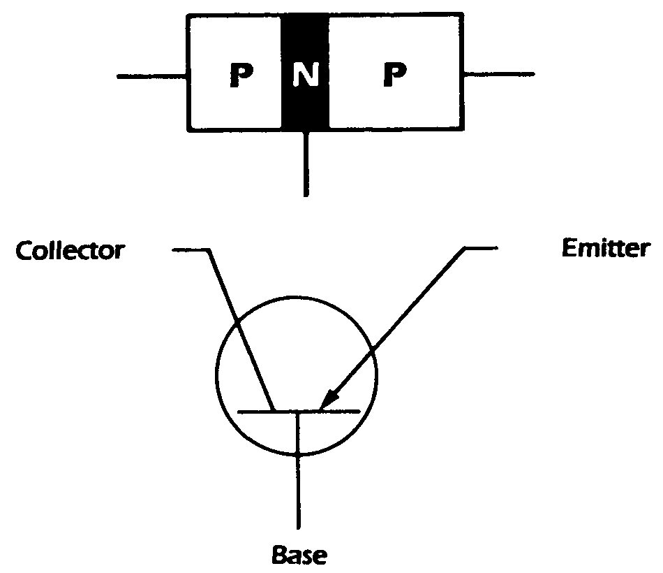
Toyota and Lexus ECUs use transistorized output drivers to operate injectors, relays, solenoids and warning circuits. Many loads receive power from a relay and are switched to ground by the ECU, although the control method varies by circuit. The donor wiring diagram must therefore establish the load feed, control side and any suppression device before testing begins.
On an engine-swap harness, a missing output does not by itself prove that the ECU driver has failed. The ECU may be withholding the command, the load may have lost its feed, or a shorted load or harness may have forced the driver into protection. Diagnosis should compare requested command, circuit voltage and load condition without applying uncontrolled power to an ECU terminal.
| Check | Expected Evidence | Diagnostic Meaning |
|---|---|---|
| Driver load supply | The relay, solenoid, injector, lamp or other load receives the feed specified by the donor diagram while the circuit is enabled | A missing or collapsing feed is a supply-path fault; it does not prove the ECU switching transistor has failed. |
| ECU command to the driver | Scan command or the required operating condition is accompanied by the correct switching or duty-cycle activity at the ECU output for that circuit design | No command directs diagnosis back to enable inputs and ECU strategy; command without output requires load, harness, protection and driver checks. |
| Switched side at ECU and load | The controlled voltage changes consistently at the ECU terminal and reaches the load without an abnormal difference between the two test points | Correct switching at the ECU but not at the load identifies wiring or terminal resistance; no switching at the ECU after prerequisites are proven raises a driver concern. |
| Load current and inductive suppression | Current follows the command and remains within the donor component specification; the turn-off waveform is controlled where the circuit uses an inductive load | Excess current or abnormal turn-off voltage can damage a good transistor, while normal electrical operation without physical response indicates a load or mechanical fault. |